Understanding the behaviour of circular diaphragm wall shafts
Please download the full case study to see all photos and figures
Circular diaphragm wall shafts are commonly used in tunnelling projects for ventilation and access, but there was limited knowledge on some aspects of the structural performance of the lining in these shafts; in particular, the development of circumferential hoop stresses in the lining had not been well understood. In addition, due to a lack of empirical data and relevant case studies for these structures, designers have taken a conservative approach to estimating ground movements associated with construction, resulting in larger predictions than would probably occur in practice. Conservative designs result in higher costs and expensive structures.
Abbey Mills Shaft F
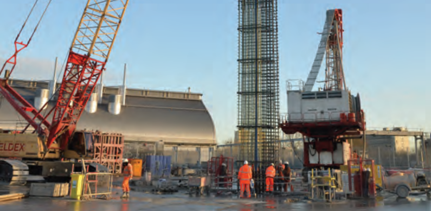
The construction of Thames Water's Abbey Mills Shaft F in East London between 2011 - 2013 provided a unique opportunity for CSIC and partners Thames Water, MVB JV, AECOM, CH2M HILL, Bachy Soletanche and UNPS, to implement an unprecedented large-scale monitoring scheme to assess the shaft lining structural response as well as ground movements associated with the construction of deep diaphragm wall shafts. With a depth of more than 70m and a diameter of 30m, Abbey Mills Shaft F is one of the largest shafts ever built in soft ground conditions in the UK. The shaft had to pass through mixed and challenging ground conditions including made ground, alluvium, river terrace deposits, London Clay, Lambeth Group, Thanet Sand and chalk. This major engineering scheme forms an integral part of the Lee Tunnel and Thames Tideway Tunnel projects, helping to stop sewer overflow and improve water quality in the River Thames.
Monitoring with fibre optic and conventional instrumentation Monitoring at Abbey Mills Shaft F included both fibre optic (FO) and conventional instrumentation.
Fibre optic monitoring1 FO cables were installed in three of the twenty 1.2m thick and 84m deep diaphragm wall panels that made up the primary lining of the shaft (Figure 1). The panel reinforcement cage was instrumented with three FO cables to measure bending strain along the entire depth of the wall as well as hoop strain at predefined locations. This marked the first use of fibre optics to measure bending and hoop response in a deep underground diaphragm wall. Installation involved two stages: (1) a pre-installation on the first reinforcement cages for each panel when the cages were still lying on the ground; and (2) the main installation when the remaining cages were lifted into position, welded to the cages underneath before being lowered into the bentonite-filled trench. Baseline readings were taken before and during shaft excavation until the final excavation depth was reached. The installation was part of a live project so CSIC had to ensure only minimal disruption to the construction process. The results were compared to predictions obtained from a finite-element model of the shaft using the Plaxis software package.
Conventional monitoring2 Conventional monitoring was used to measure wall and ground movements associated with the shaft excavation. Instrumentation included manual inclinometers (lateral movement), multi-point automatic rod extensometers (vertical movement) and magnet extensometers installed in boreholes in the surrounding ground, as well as surface levelling pins. In addition, manual inclinometers were installed in the diaphragm walls of the shaft to measure wall deflections. Interpreting measurements from inclinometers is known to be challenging and CSIC took steps to correct accumulated errors. The ground movement measurements were compared to an existing empirical method proposed by New and Bowers (1994)3 to validate its applicability to deep diaphragm wall shaft excavation. The wall movements were compared to numerical predictions obtained from a numerical parametric study using FLAC2D software
Key findings
The monitoring of Abbey Mills Shaft F provides new information that has implications for the future design of deep circular excavations: • inclinometer/extensometer data showed very small wall movement (maximum deflection of 4mm) at the final shaft excavation depth which is in good agreement with numerical calculations • the overall ground settlement was very small - max 8mm settlement during wall construction, and heave of about 5- 10mm likely during excavation. In contrast, empirical predictions of settlement were up to 40mm • FO measurements showed that the overall radial movement of the diaphragm wall was very small. During excavation the measured hoop and bending strains of the wall, principally in the chalk, exceeded the predictions. This may have been caused by non-verticality of the walls and/or the structure may be less stiff than assumed in design due to decreasing effective wall thickness with depth.
Monitoring delivers cost savings and assurance
As a result of ground movements being considerably less than the design predictions, an estimated cost saving of at least £10 million in risk mitigation will be saved for future Thames Water construction projects. Additionally, monitoring has provided a better understanding of deep circular shafts and diaphragm wall shafts to improve future design to save time, materials and money, ultimately delivering a more sustainable and affordable structure.
This project won the Fleming Award 2013 from the Institution of Civil Engineers
Project contact Dr Mohammed Elshafie, CSIC Co-Investigator, me254@cam.ac.uk
1 Schwamb T, Soga K, Mair RJ et al. (2014) Fibre optic monitoring of a deep circular excavation. Proceedings of the Institution of Civil Engineers – Geotechnical Engineering 167(2): 144–154.
2 Schwamb T, Elshafie M, Soga K, Mair RJ (2016) Considerations for monitoring of deep circular excavations. Proceedings of the Institution of Civil Engineers – Geotechnical Engineering Vol 169 Issue GE6, pp.477-493.
3 New BM and Bowers KH (1994) Ground movement model validation at the Heathrow Express trial tunnel. In Tunnelling ’94. Springer, Dordrecht, the Netherlands, pp. 301–329.
